射频同轴连接器选型与仿真 Rf coaxial connector selection and simulation
什么是射频同轴连接器?
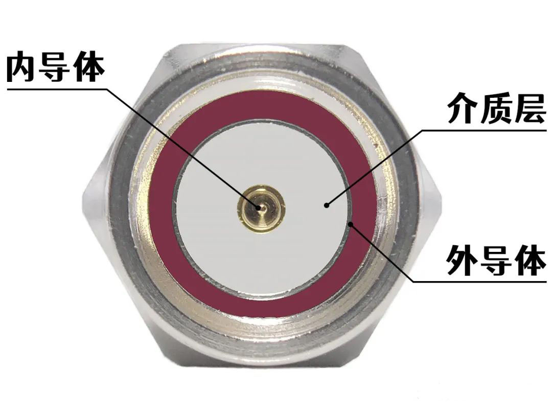
在入门学习微带贴片天线仿真的时候,我们往往采用简单的波端口或集总端口进行激励。但是实物加工测试的时候,就有必要加入一个射频同轴连接器。其主要作用是为了实现设备/模块之间的互联,有效传递射频、微波信号。射频同轴连接器通常由内导体、外导体、绝缘体以及连接结构等部分组成。
同轴连接器的分类?
常用的射频同轴连接器的类型有:
SMA(SubMiniature version A)连接器:一种应用广泛的小型射频同轴连接器,具有体积小、频带宽、性能稳定等特点,一般上限工作频率为18GHz,现在部分厂商已经可以将SMA最高频率做到26.5GHz。
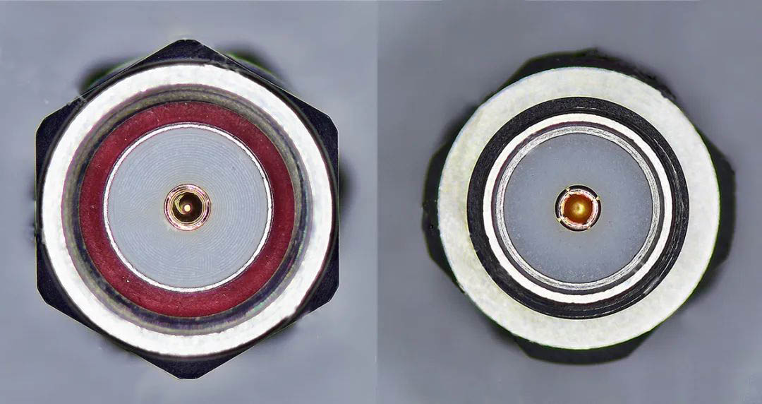
SMA界面图
SMP(SubMiniature Push-On)连接器:一种超小型推入式射频同轴连接器,SMP连接器的尺寸非常小,有助于实现设备的小型化和高密度集成,适用于空间受限的应用场景。其通常能在较宽的频率范围内工作,DC到40GHz,甚至部分型号可更高。
![]()
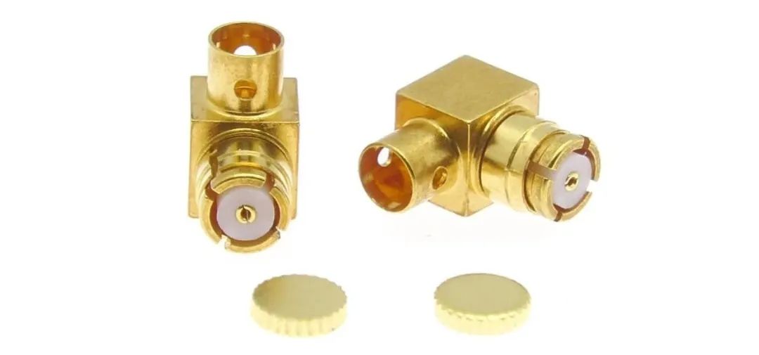
SMP连接器
N型连接器:N型连接器是一种常见的射频连接器,其插头和插座都具有密封性能,能够承受高功率、高电压和高频率的应用环境。N型连接器采用一种内螺纹设计,可用于在射频和微波设备和系统中传输信号。它是一种通用性高、频率范围广、使用方便、可靠性高的连接器。N型连接器通常有50欧姆和75欧姆两种规格,其频段范围可从0GHZ至11GHz,有些型号甚至能够达到18GHZ,因此N型连接器被广泛应用于雷达、天线、卫星通讯、微波测量等领域。N型连接器的优点包括机械强度大、防水防尘性能好、抗老化性能强、性能稳定、易于安装和拆卸、接触和信号传输性能优良等。此外,N型连接器的缺点是体积较大,不能满足高密度集成的要求,同时价格也比其它类型的连接器略贵。
![]()
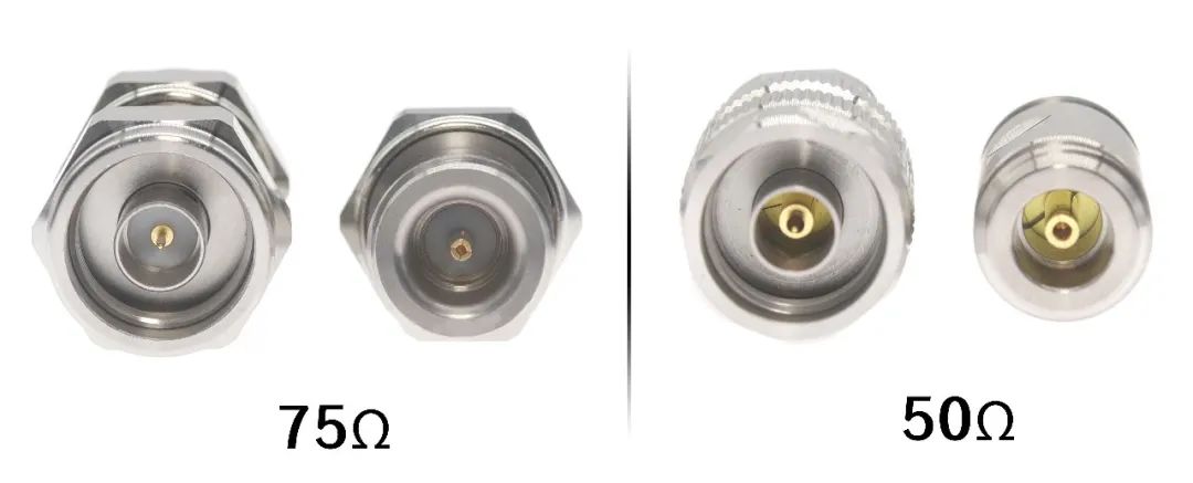
N型连接器
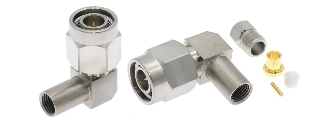
TNC(Threaded Neill–Concelman)连接器:TNC 连接器采用螺纹连接方式,相比一些卡口式连接,连接更为牢固,在振动等环境下也能保持稳定的连接,具有良好的抗震性。例如在一些移动通讯设备中,即使设备经常受到振动,TNC 连接器也能确保信号的稳定传输。
TNC连接器
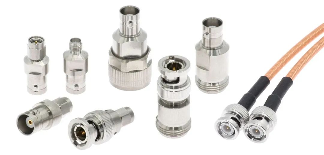
BNC(Bayonet Nut Connector)连接器:常用于视频监控、仪器仪表等领域。一般支持的信号频率范围为 0 到 4GHz,有高精度的 BNC 连接器频率可达 12GHz 或更高。常见的特性阻抗有 50 欧姆与 75 欧姆两种,其中 50 欧姆的 BNC 连接器主要用于射频信号传输等大多数射频应用;75 欧姆的 BNC 连接器则常用于广播、音频 / 视频和低频通信等结构。
![]() BNC转接器
BNC转接器
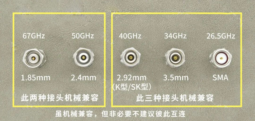
除此之外,在射频同轴连接器中,有时候还有2.4mm/3.5mm/2.92mm连接器这些代称。它们通常是指连接器的尺寸规格或接口类型,代表不同的连接器特性和应用场景。
2.4mm 连接器:具有非常高的频率范围,可支持到 50GHz 甚至更高。它的尺寸相对较小,具有低反射和低损耗的优点。主要用于极高频率的射频系统,如高端测试设备、毫米波通信等领域。 2.92mm 连接器:具有较高的频率范围和低损耗特性。它的工作频率可以高达 40GHz 甚至更高。常用于高频测试测量设备、微波通信系统、雷达等对频率要求较高的领域。 3.5mm 连接器:其频率范围通常可达到 26.5GHz 左右,最高可达34GHz。相比 2.92mm 连接器,它的尺寸稍大一些。在一些中高频的射频应用中较为常见,如通信设备、电子测试仪器等。
如何选择连接器
对于我们射频和天线设计而言,常用的射频连接器集中在SMA和SMP类型。大家根据自己所需的频段选择对应的连接器大类。不过,在实际应用中,选好大类后还有进行小类别细分。这里就需要根据实物设计的装配方式来因地制宜了。
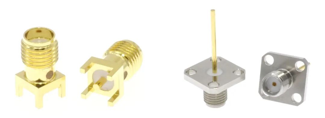
例如,侧馈式和背馈式微带贴片天线就可以分别选择下图两种SMA连接器。
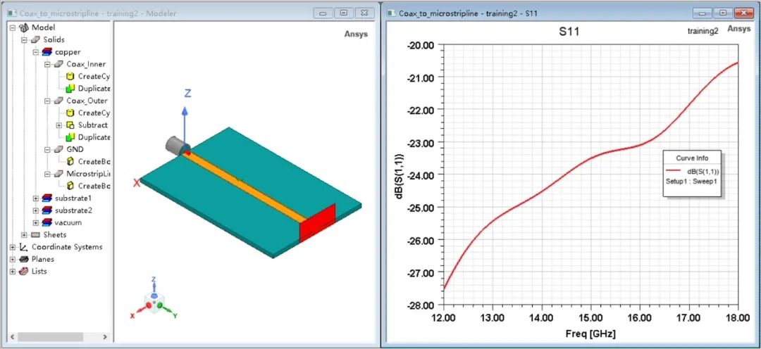
 虽然这些连接器是按50欧姆标准进行设计的,但实际馈电中若不进行电磁仿真,很容易造成端口失配的现象。以50欧姆同轴线和微带线级联为例。下图所示的仿真模型仅考虑理想的同轴线与微带线级联,其同轴线的端口反射系数在12~18GHz内均小于-20dB。
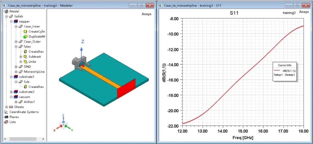
如果仿真完后直接去买来一个射频同轴连接器焊接上进行测试,我们就会发现端口反射系数在高频会迅速恶化。这是因为连接器上的法兰盘多了2条金属柱,造成了阻抗的不匹配现象。
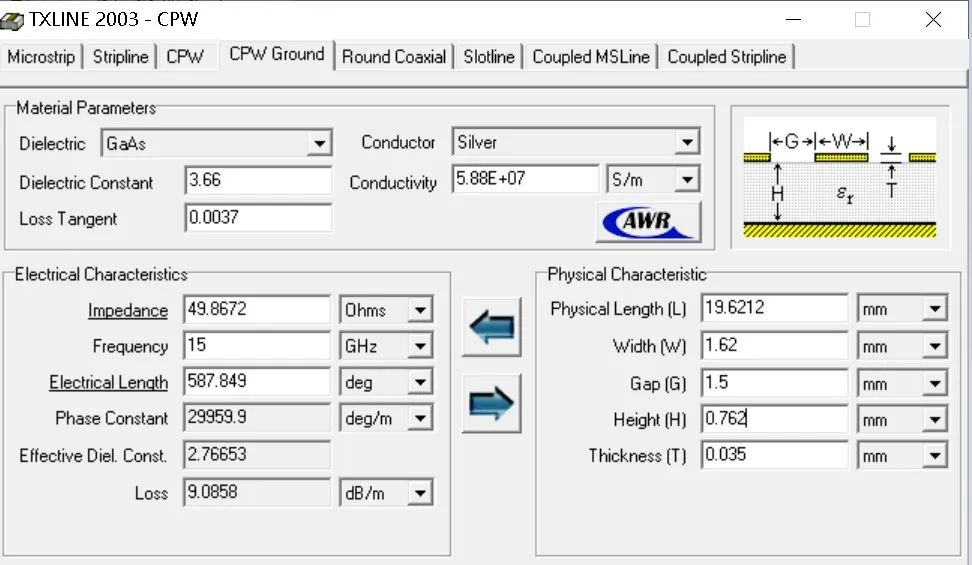
为了优化传输系数,我们可以考虑在金属柱下方增加2条接地的矩形条,利用Txline大致计算这种结构下应该设置多大的GSG间隙。
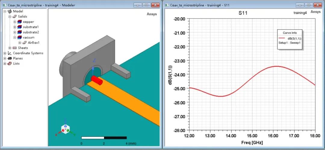
选择合适的射频连接器,可以看出端口仿真系数就没有问题了!
如果连接器种类已经没办法更改了,还有什么其他方法来缓解这个现象么?
①可以尝试手动将法兰盘上金属柱的长度剪短一点。
②同样用Txline,重新选择合适的线宽和间隙,使得计算的共面波导传输线的特性阻抗大致为50欧姆,实现50欧姆同轴线-50欧姆共面波导传输线-50欧姆微带传输线的三线转换。
看到这里,是不是就学会了万无一失了呢?NO!注意你待测试线缆的接口类型,内螺纹还是外螺纹,公头还是母头。连接器的接口需要与之相适配。
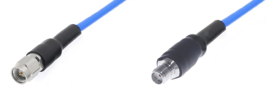
如果买错了怎么办呢?那只有买个转换器了。如果你转换器还是买错了怎么办?那就只能凉拌咯 !
!
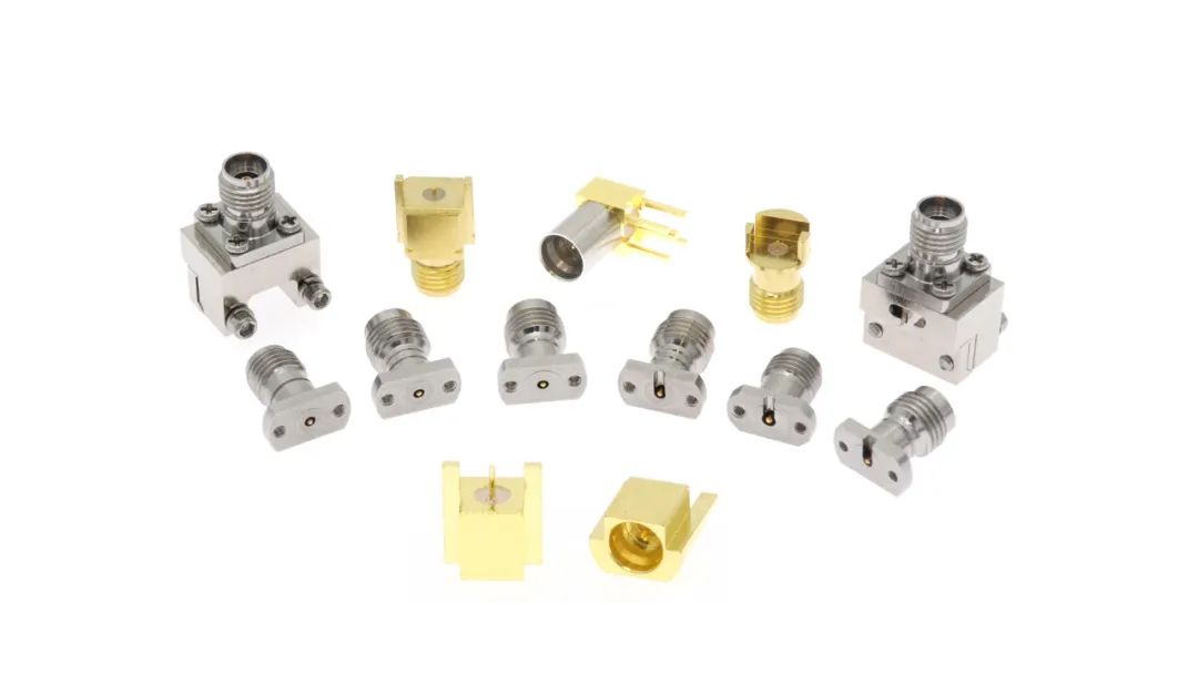 PCB连接器
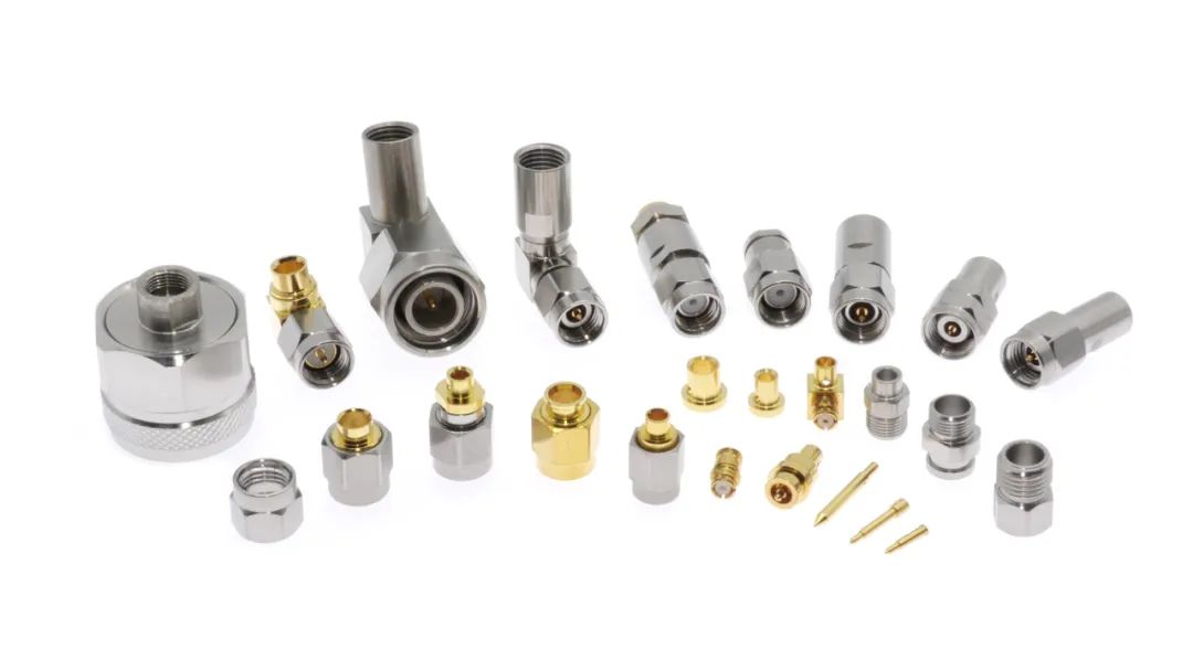 电缆连接器
电缆连接器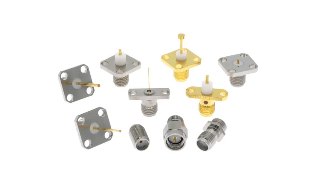
面板式连接器
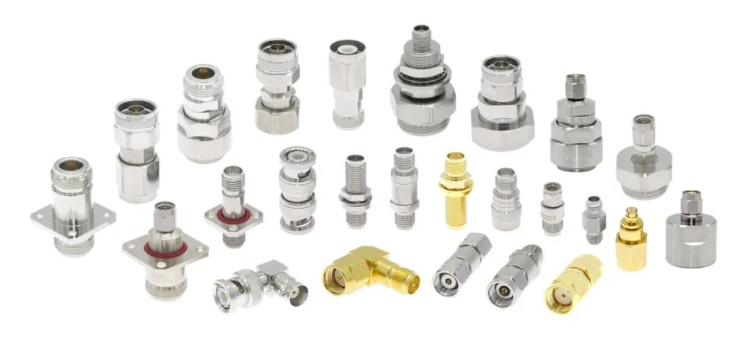
射频转接器
What is an RF coaxial connector?
When learning microstrip patch antenna simulation at the beginning, we often use simple wave ports or lumped ports for excitation. However, when the physical processing test, it is necessary to add an RF coaxial connector. Its main function is to realize the interconnection between devices/modules and effectively transmit radio frequency and microwave signals. The RF coaxial connector is usually composed of an inner conductor, an outer conductor, an insulator, and a connecting structure.
Inner conductor: usually a metal needle or metal tube, responsible for transmitting radio frequency signals.
External conductor: Usually a metal sleeve, together with the inner conductor to form a transmission channel, while playing a shielding role to reduce the impact of external interference on the signal. Common outer conductors are stainless steel and copper gold plating, and the connectors of stainless steel outer conductors are usually more durable and have higher manufacturing costs.
Insulator medium: located between the inner conductor and the outer conductor, plays the role of electrical insulation to prevent short circuit between the inner conductor and the outer conductor. Common filling media are PTFE and air media, etc. In order to make the connector have a higher cutoff frequency, some cases will also be filled with air with lower dielectric constant and insertion loss.
Connection structure: used to realize the connection between the connector and other devices, usually including threaded connection, bayonet connection and so on. For example, flanges are mainly used to securely install RF connectors on equipment panels or other structures. Through bolts, nuts and other fasteners, the flange can be tightly attached to the mounting surface to ensure that the connector will not loosen or fall off during use. In addition, in some applications, flanges can also provide a sealing function to prevent external environmental factors such as dust and moisture from entering the interior of the connector, thereby protecting the connector and the connected device.

Classification of coaxial connectors?
Common types of RF coaxial connectors are::
SMA(SubMiniature version A) connector: a widely used small RF coaxial connector, with small size, wide frequency band, stable performance and other characteristics, the general upper limit of the operating frequency of 18GHz, now some manufacturers have been able to SMA maximum frequency to 26.5GHz.

SMA interface diagram
SubMiniature Push-On (SMP) connector: An ultra-miniature push-in RF coaxial connector. The SMP connector is very small in size, which helps to achieve miniaturization and high-density integration of devices, and is suitable for space-limited application scenarios. They typically operate in a wide frequency range, DC up to 40GHz, and even higher for some models.![]()

SMP connector
N-type connector: N-type connector is a common RF connector, its plug and socket have sealing performance, can withstand high power, high voltage and high frequency application environment. N-type connectors feature an internal threaded design and can be used to transmit signals in RF and microwave devices and systems. It is a connector with high versatility, wide frequency range, easy to use and high reliability. N-type connectors usually have 50 ohm and 75 ohm two specifications, the frequency range can be from 0GHZ to 11GHz, and some models can even reach 18GHZ, so N-type connectors are widely used in radar, antenna, satellite communication, microwave measurement and other fields. The advantages of N-type connectors include high mechanical strength, good waterproof and dustproof performance, strong anti-aging performance, stable performance, easy installation and disassembly, excellent contact and signal transmission performance. In addition, the disadvantage of N-type connectors is that they are larger in size and cannot meet the requirements of high-density integration, and the price is slightly more expensive than other types of connectors.
![]()

N-type connector
TNC(Threaded Neill - Concelman) connector: The TNC connector is threaded. The connection is stronger than some bracket connections and can maintain stable connection in vibration and other environments, with good shock resistance. For example, in some mobile communication equipment, TNC connectors can ensure the stable transmission of signals even if the equipment is often subject to vibration.

TNC connector
Bayonet Nut Connector (BNC) : commonly used in video surveillance, instrumentation and other fields. Generally supported signal frequencies range from 0 to 4GHz, with high-precision BNC connectors up to 12GHz or higher. The common characteristic impedance is 50 ohm and 75 ohm, of which 50 ohm BNC connector is mainly used for most RF applications such as RF signal transmission; The 75 ohm BNC connector is commonly used in structures such as broadcast, audio/video, and low-frequency communications.

BNC adapter
In addition, in RF coaxial connectors, sometimes there are 2.4mm/3.5mm/2.92mm connectors. They usually
refer to the size specifications or interface types of connectors, representing different connector characteristicsand application scenarios.
2.4mm connector: has a very high frequency range and can support up to 50GHz and beyond. It is relatively
small in size and has the advantages of low reflection and low loss. It is mainly used in extremely high frequency
RF systems, such as high-end test equipment, millimeter wave communication and other fields.
2.92mm connector:High frequency range and low loss characteristics. It can operate at frequencies as high as40GHz and beyond.
It is often used in high-frequency test and measurement equipment, microwave communication
system, radar and other fields with high frequency requirements.
3.5mm connectorIts frequency range can usually reach about 26.5GHz, up to 34GHz. It is slightly larger than the
2.92mm connector. It is more common in some medium and high frequency RF applications, such as
communication equipment and electronic test instruments.

How to choose a connector?
For our RF and antenna designs, common RF connectors are concentrated in the SMA and SMP types. We choose the corresponding connector category according to the frequency band we need. However, in practical applications, there are small category subdivisions after the selection of large categories. Here it is necessary to adapt to local conditions according to the assembly method of physical design.
For example, side-fed and back-fed microstrip patch antennas can be selected from the two SMA connectors shown below.
 Although these connectors are designed according to the 50 ohm standard, it is easy to cause port mismatch if electromagnetic simulation is not carried out in the actual feed. Take 50 ohm coaxial line and microstrip line cascade as an example. The simulation model shown in the following figure only considers the ideal coaxial line and microstrip line cascade, and the port reflection coefficient of the coaxial line is less than -20dB in 12~18GHz.
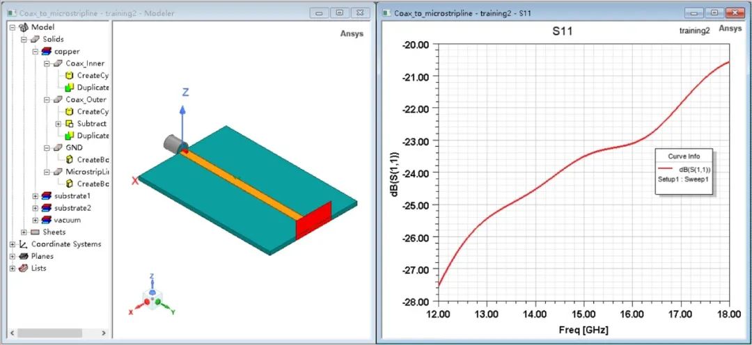
If you buy an RF coaxial connector directly after the simulation and test it, we will find that the port reflection coefficient will deteriorate rapidly at high frequencies. This is because there are two more metal columns on the flange of the connector, resulting in a mismatch of impedance.

In order to optimize the transmission coefficient, we can consider adding two grounded rectangular bars under the metal column, and use Txline to roughly calculate how much GSG gap should be set under this structure.

Choose the right RF connector, you can see that the port simulation coefficient is no problem!

If the connector type can not be changed, what other ways to alleviate this phenomenon?
①You can try manually cutting the length of the metal column on the flange.
②With the same Txline, suitable line width and gap are re-selected, so that the characteristic impedance of the calculated coplanar waveguide transmission line is roughly 50 ohm, and the three-wire conversion of 50 ohm coplanar waveguide transmission line to 50 ohm microstrip transmission line is realized.
See here, did you learn to be foolproof? Noooo! Note the connector type of the cable you are testing, internal or external threads, male or female. The interface of the connector needs to be adapted to it.

What if I buy the wrong one? Then we'll have to buy a converter. What if you still bought the wrong converter? Then it can only be cold salad pictures !
!
 PCB connector
 Cable connector

Panel connector

RF adapter
上一篇:端子压接标准及剖面要求 下一篇:连接器行业分析
Previous: Next:Connector industry analysis


